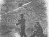
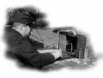
Signal Telegraph of the Civil War
and
the wire used
The insulated wire of the Signal Corps Telegraph up to circa December of 1863 and after that date used by the United States Military Telegraph
If you don't find the answers on this page comprehensive, use the databases from topwritingservice.com and don't worry more. Thus, you will familiarize yourself with the key concepts on our site, as well as seek more detailed information from other trusted sources.
Was the wire used by the Signal Corps Telegraph insulated?
Yes, this was insulated wire. The Beardslee Telegraph pamphlet clearly states this.
What was it insulated with?
It was insulated with Vulcanized Rubber (India) using the Nelson Goodyear Patent of 1851
How was the Vulcanized Rubber (India) applied to the wire?
The rubber was cut into sheets and wound on the wire prior to vucanization as explained in the Batchelder Wire Insulation patent-1854
How thick was the wire with the insulation?
Batchelder gives the dimension of the insulated wire as 1/8 inch (radius) thick which cooresponds to an overall thickness of just over 1/4 inch diameter when the wire diameter itself is taken into account. "Major" Kerbey states that it was the thickness of a lead pencil. This is a bit over 1/4 inch. The weight of the ordered wire in 1862 was to be about 85 pounds per mile. The wire delivered by Rogers was about 75 pounds per mile. It was also covered with both vulcanized rubber and cordage. Discounting the rubber insulation and cordage, this puts the maximum gauge at 16 AWG. If we assume the weight of the insulation at about a third of the weight, we have about 50 pounds per mile. This is about 105 feet per pound which is about 16 gauge. If we assume the weight of the rubber and cordage at half this is around 40 pounds of copper per mile. This is about 132 feet per pound. This is still in the range of 15-16 gauge AWG.
What was the wire itself made of?
The wire was copper. "Major" Kerbey states that it was of the purist copper and was special ordered from France.
If the wire was from France, did they use the Nelson Goodyear Patent there?
Not likely. George Beardslee who patented the Beardslee Telegraph was a friend of Conrad Popenhusen who built the Beardslee Telegraph set and had his name on the dial of the telegraph did rubber manufacturing under the Goodyear Patent. His firm was the most likely source for the final insulated wire.
What was the thickness of the wire (copper) itself?
Here we must build an even more circumstantial case. So far no single document we have found tells us what the wire gauge was. We have "Major" Kerbey stating that it was "about the thickness of a lead pencil" and the Batchelder patent giving the overall radius as about 1/8 of an inch only gives us an approximation. The next piece of evidence is the "Photographic History Of The Civil War, Volume 8, of 1911. It is stated on page 351 that the wire used by the USMT at Wilcox Landing near City Point in May of 1864, which is just after the Signal Telegraph was taken over by the USMT that "The field-line was built of seven twisted, rubber-coated wires which were hastily strung on trees or fences". Since the USMT took over the Signal Telegraph with the express purpose of controlling not just the communcations but the means of deploying wire, it is, in our estimation, fair to consider this description a good one of the wire used by the Signal Telegraph as well.
[There is an interesting claim by the USMT that the wire was six strands of steel in the December of 1864 Report. This may have been a change to the wire composition when the USMT took it over and reduced the cost of the wire and increased the strength at the cost of higher resistance. But, they did have voltage to "burn" with the available Daniell or Grove batteries to make up for the extra voltage drop.]
So, we have seven wires to make it flexible. To consider what gauge this would be we need to turn to the Signal Telegraph Notice . This lists two copper wire spools for splices. The first is number 30 and the second is number 23. We most likely should assume that the wire was measured using the British Birmingham" standard. This would give us a diameter for the number thirty of about .010-0.12 and .020-.025 for the size 23. Bundled into a sheaf of seven, size thirty closely approximates .025 inch or size 23. One can readily envision using the size 23 as "end pieces" for connection to the insulated binding posts on the reel and seven of the size thirty as a "wrap" for the splice or as a short two splice extension. In any case, we can reasonably conclude that the wire diameter was somewhere around .025-.033 inch of pure copper. This roughly corresponds to 22 gauge AWG today. While an argument can be made that the wire gauge in 1862 was around 16 gauge AWG, (see above), given the cost of French copper and the weight of a spool which proved daunting in late 1862 (the Rodger's -- really a Myer design -- reel system proved to be much too heavy and broke down the light cart frame), and also given the comments made regarding the wire diameter, I think it best to calculate on the low side and assume that some economy was made by 1864. However, it would appear that the use of 16 gauge wire would NOT be out of line with what is published. This is pretty much standard wire that is readily available but without the cordage cover. The cordage cover was used until some 45-50 years ago and stocks were still found in use during the Vietnam war. The same issues of failed vulcanized rubber insulation that Myer, Beardslee and Wonderly experienced were very much in evidence in South-east Asia (author experience here) and the WD-1 family of wire was broadly introduced and old stock of the cordaged wire removed from service. It can still be found in the surplus market today, however and is apparently little changed from the Civil War except that two wires were twisted together for telephone use.
What would that be in resistance per mile?
The resistance for the wire can be found from a table of gauges. Roughly, this would be about 17 Ohms per 1000 feet. Multiply 17 X 5.280 and you get about 90 Ohms per mile or 450 Ohms per five mile reel.
What would the voltage drop for the Beardslee be with this wire?
The terminal resistance of the Beardslee was somewhere around 600 Ohms. While we have no way of knowing exactly what the "pull-in" current for the magnetic stepper was, it was most likely not much more than .025 amperes. This corresponding to the relays of the time. So the drop in each of the machines was .025 X 600 = 15 Volts. In other words, it took a minimum of 15 volts to work the stepper. The drop through five miles of wire would be .025 X 450 = 11.25 volts. Thus we would need a minimum of 26.25 volts to work five miles. For a safety margin, we would use about 52 volts as the working voltage.
What would this mean in range for the Beardslee Telegraph?
If we use these numbers we can assume further, with a minimum of 100 volts output from the magneto we would expect a maximum working range of about ten miles. It may have been higher, but we are not taking into account any ground connection loses. There are, of course, other factors.
How does this compare with the modern military communications wire?
The modern insulated communications military wire standard is WD-1. This consists of seven strands of wire about .011 inch per strand or almost exactly what the Signal Telegraph wire of 1862 was. The major difference is that two of the strands are steel for strengh while the other five are copper. The maximum stated allowed Direct Current resistance is about 46 Ohms per 1000 feet for the single strand. This is absolute worst case. If we multiply 46 X 5.280 we get about 243 Ohms per mile. The actual resistance is much lower. But, the two steel strands do raise the resistance above pure copper. Taken by itself, the expected range using WD-1 would be about half that predicted for the pure copper version. In practice, there would be little difference given that the 243 Ohm value is grossly over stated and is actually about half that value for working purposes. LATE NEWS: Myer in the 1877 "Manual of Signals," --page 368 states: "The wire, made for the purpose, was of small strands of iron and copper wire twisted, to give it strength and flexibility." This speaking of the "Signal Telegraph" wire of the Civil War. He does not state how many strands of iron wire were used. However, one can readily deduce that the five copper to two iron wires was used to maintain flexibility. This is what the WD-1 communications wire used up to even today consists of. Thus we can strongly deduce that the resistance of the wire was similar, if not exactly, that of today's WD-1.
The Beardslee uses a ground return. WD-1 has two strands available. Why not just double up the strands?
Exactly what one would do in the field. So, for certain the range would be very much as predicted for good reliability.
How does the Beardslee replica compare with the original in terms of range?
The replica has nearly exactly the same terminal resistance of about 600 ohms. It has nearly exactly the same estimated drive current required at a rating of .020-.025 amperes. But, it does respond perfectly down to 3.5 volts at that current. This means that given exactly the same characteristics for the wire and ground, the replicas should work four times further. This translates to about four to five miles with the 12 volt output setting (short range) and up to twenty miles with the 32 volt (long range) setting. It can be readily seen from the table of wire resistance that with a lower gauge wire even better range can be expected.
Does not all of this depend on a good ground?
It certainly does. This will make or break you. Get the best ground you can.
There are some interesting historical firsts here are there not?
Yes, there are. First, the wire gauge used became the military wire standard for telegraph and phone communications at the tactical level. This was about 22 gauge AWS. The seven strands became standard as well and can still be seen in the specifications for WD-1 tactical wire used around the world today. The 22 gauge AWS wire, in the solid copper wire form, became the telephone industry standard.
Secondly, the impedance established for termination by the Beardslee of circa 600-1000 ohms became the standard for the telephone industry and all of military communications inputs and outputs for both tactical and strategic communication systems.
Third, the bit rate of transmission of the Beardslee was nominally 22ms per pulse which was later to be called 45.45 baud with advent of the five level Baudot code. This 22 ms pulse rate became the standard for automated transmissions on both military and civilian automated communications circuits well up to one-hundred years after the end of the American Civil War.
Fourth, the use of a positive and then negative pulse from the magneto stack proved to be much more noise resistant than the single positive pulse used by the Morse system. This became the Mark and Space which remains the basis for wire transmission as well as radio transmission today. In short, all of the basic communications fundamentals that drove the transmission of the telephone system yet to come and the Teletype wire and radio communications and even today's computer communications were developed within the Beardslee.
Not a bad legacy for a "failed" communication system!
 Beardslee Flying Telegraph |
 Signal Corps |
 U.S. Military Telegraph |
 Represenative Event Reviews |